Quantcast
Channel: The 21st Century Digital Home
Viewing all 157 articles
Browse latest View live

Esplora Expansion Header Pinouts

$
0
0
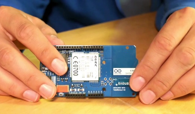
As most know, the new Arduino Esplora has an expansion header on the front which is not compatible with previous Arduinos like the Uno, Mega, or Leonardo.  It is documented as for a display that will be coming later.

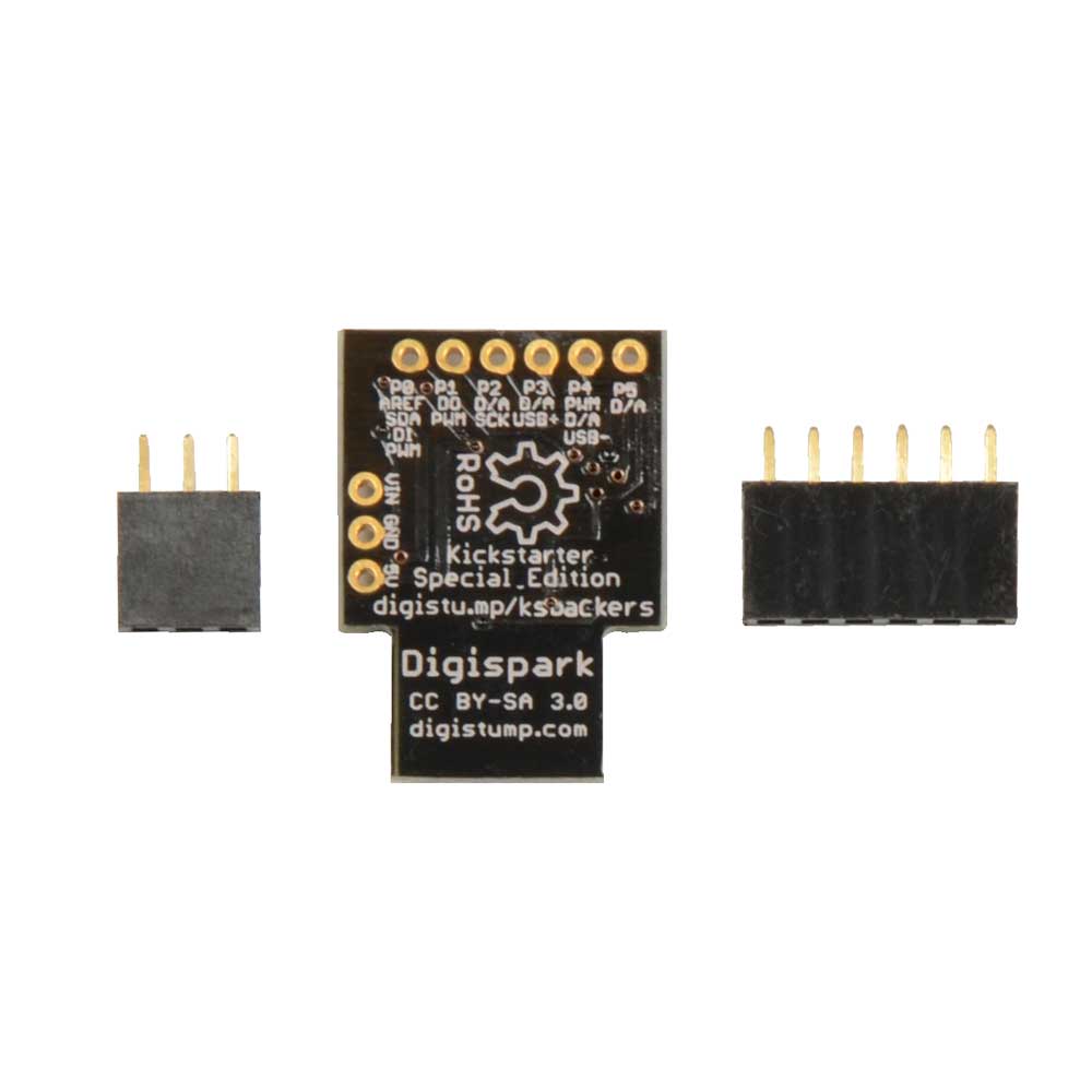
As the device encourages hacking (as do all Arduino products, thank you Open Source), I have worked to document the pinouts of the expansion headers.  This is my poking and not an official release but it is based on the officially released schematic and electrical and software testing on my part.
The left expansion header (closest to the joystick) appears to not be electrically connected and may only serve to provide a mechanical standoff for the proposed display.  It is the right ten pin header (nearest the 4 buttons) that corresponds to the schematic.  I have designated Pin 1 as the topmost (the top having the USB and white/orange ports) and Pin 10 being at the bottom (the end with the linear sliding resistor).

My interest stems from expanding the capabilities of the Esplora.  Yes it has many sensors and displays, but I may wish to add a sensor.  But more importantly to connect it to the Internet of Things (or to act as a good controller), it should have wireless communication.  So I have connected the Esplora via hard serial and soft serial with good results.

Note: the Esplora has dedicated the pins for another use - we are repurposing the display pins fo this will not work well with both something else and a display connected (you might be able to do something but it is beyond this post).

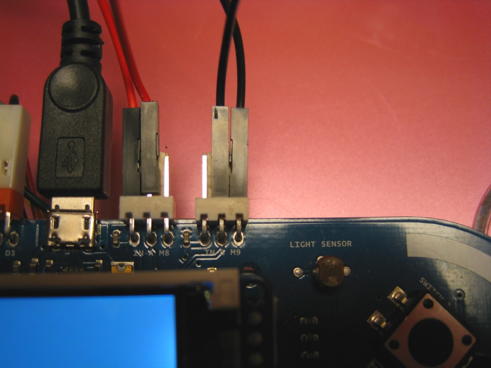
The hardware serial, Digital Pins 0 and 1 which are Serial Receive and Transmit on classic Arduino Uno etc. map to the Esplora right expansion header pins 7 and 8.  On the Uno they are shared with the USB port but on designs based on the Leonardo like the Esplora, the hardware serial is connected separately.  Software-wise, this means the Serial() function talks to the USB.  The Serial1() function talks to the hardware serial pins.  The SoftwareSerial library works on Leonardo based designs but the receive pin only works on classic I/O pins 8, 9, 10, 11, 14 (MISO), 15 (SCK), and 16 (MOSI) according to a comment in the SoftwareSerial example.  I confirmed the hardware receive pin will not work as the software serial receive (transmit works though).  Here is a wiring diagram for the SoftwareSerial.  Note the ground and 5 volt pins are connected also.

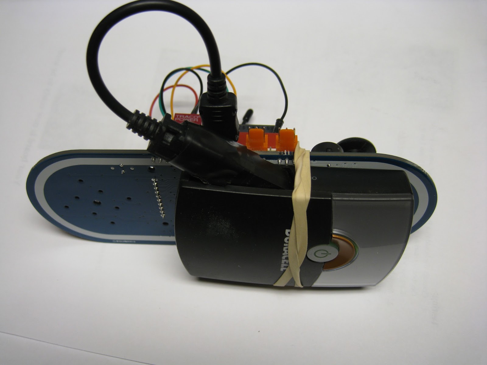
I use a TTL serial to USB device called a Foca from IteadStudios but a FTDI Friend or similar is fine.  It should be 5 volt compliant (as the Esplora is a 5 volt Arduino).  Biggest note: the Esplora Transmit (expansion pin 8) should connect to the receive of the device and the Esplora Receive (hardware is expansion pin 7 for hardware, one of the others like expansion pin 6 for softwareserial).

The software examples for hardware and software serial connection are posted at https://github.com/TheKitty/EsploraSerial

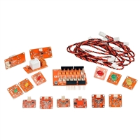
Next up is connecting the serial lines to an Xbee radio.  Another idea is more sensors (!) - a mini-breadboard like this will fit between the headers, have fun.


Arduino Esplora Display Preview

$
0
0
Ok, so I am not releasing an LCD for the Arduino Esplora myself.  But in my documentation of the Esplora expansion header (here), I started to notice something from the schematic.
There is no information on the "future display option" other than the released schematic, the press release, and the device info page. The schematic states a 128x160 color display.  The device info states the connector is for "TFT display connector connector for an optional color LCD screen, SD card, or other devices that use the SPI protocol."  It also has the "CD_CS" / "CS-SD" line which seems to confirm a SD card option.

Ok, now where have I seen this . . . browsing the Adafruit displays, I find what I was looking for.  The Adafruit 1.8" display has the exact pinout, resolution, and a micro-SD card slot.


The display is very nice and there is a good library for both text and graphics.  It is not fast (the library could use some speed optimizations) but it is a "shaken out" piece of gear and code.  See the new Adafruit Learning Center tutorial for more information.  Note the tutorial uses an Arduino Uno and not an Esplora.

I note only one anomaly. The Adafruit display pins have pin 1 as a "Lite" backlight pin (which may be pulse-width modulated (PWM) for intensity) with pin 9 as the VCC power pin.  The Esplora schematic has pin 9 as the "BL" (backlight?) and pin1 as +5V.  As both these pins on Esplora are at 5 volts, it would work but the backlight is always on.

Would it not make sense to connect one of the PWM lines of the Esplora's Atmel microcontroller chip to the backlight to provide intensity control?  It would but all these lines are used for onboard items: the RGB LED, the buzzer, the "D13" yellow LED, and the two orange TinkerKit connectors on the top.  None are left for the backlight.

I have a different Adafruit LCD but not the 1.8" unit so I cannot test this today.

It could be that the Arduino team will release their own branded display.  But then again they could be working a combined effort with Adafruit (like their recent collaboration on the Arduino Micro).

I would say that the Adafruit display will not be the exact display sold for the Esplora - the SD Card slot would rub the left expansion header which is not connected to anything but should serve as a mounting point.  It would then be very likely that the unit to be released will be nearly identical but have the SD card on one of the long sides and the left edge have a 10 pin header to press into the connector providing a good mechanical fit (that is easily taken off if desired given the learning side of this device).

Last note - it is interesting that they decided on their own display rather than the TinkerKit LCD (as they have four TinkerKit connectors up top).  My take is cost as the TinkerKit version has it's own microprocessor, making it a more expensive option and adding bulk.

Arduino Esplora interfaced to an Xbee Radio

$
0
0
Third in a series, I expand on my previous post documenting the Arduino Esplora expansion header and using the hardware and software serial capabilities of the Arduino on the Esplora platform.
For this post, I use a small perfboard and some header to make a plug-in platform for the Xbee project.  To aid prototyping, I use a small breadboard available from most electronic outlets.  You can use the same concept to prototype any circuit you like with the Esplora using the expansion pins I document here.
A perfboard with headers used to anchor it as a base

On the breadboard, I mount an Xbee adapter board (similar to Sparkfun board, also use headers).  As the Xbee operates at 3.3 volts and the Esplora is a 5 volt system at the expansion header, I use a voltage regulator (one from Adafruit was handy but you can make your own 5v to 3v3 circuit, see Igoe Making things Talk, pages 200-201).  Per Igoe, the Xbee data lines are 5 volt tolerant so I interface them directly.

Esplora connections: Pin 10 ground (black), Pin 9 +5 volts (red), Pin 8 Transmit (orange), Pin 7 Receive (green).  +5 goes to the regulator input and the regulator output goes to Xbee pin 1 VCC.  Connect ground to the regulator and XBee grounds.  Note: The receive line pin 7 from Esplora goes to Xbee transmit pin 2, transmit line from Esplora header 8 connects to Xbee receive pin 3.  That's basically it on wiring, not fancy when you know what you are connecting to.
Mounted breadboard with regulator, Xbee carrier and Xbee.  Wiring from the Esplora right header to the breadboard.

For software, I take the lead from my previous post on pin mapping.  The Esplora hardware serial line follows Leonardo conventions.  The Serial function talks to the USB.  The Serial1 function talks to the "D0/D1" hardware serial line we know from programming older Arduinos like the Uno.  These are on Esplora header pins 7 and 8.  Software serial is possible too although the receive pin must be another data line that supports the softwareserial library's interrupt function.  Here I stick with the hardware serial and it is simpler.

I took the Arduino software IDE example sketch "EsploraRemote" and added just the tiniest tweeks to change use of the serial port (USB) to the hardware serial line Serial1.  The code is available as EsploraXbeeRemote at https://github.com/TheKitty/EsploraSerial .  The code is simple but cool - it takes input to either change the buzzer or LED on the Esplora or return Esplora input values.

On radios, I use two Xbee Series 1 radios.  The MY addresses are set to 1 on #1, 2 on #2.  Destinations are set to the other (2 for #1, 1 for #2.  They are also set for serial communications 9600, 8, N, 1.  For Xbee basics, see Making Things Talk or the digi examples website.

Esplora with Xbee and another Xbee talking to it wirelessly
For the transmitter, I use the Foca board I used yesterday - you can use equivalent boards from Adafruit and Sparkfun - they turn a USB port into serial to talk to the Xbee or to talk TTL serial.  You can use any Xbee transmit/receive project to speak to the Esplora - the example just uses a serial terminal to talk to the Xbee which wirelessly sends and receives characters to the Esplora via the other Xbee.  I use the PuTTY serial terminal on Windows - it is available on Mac & Linux or use your favorite serial program.  I set communications to the same as the example program and my Xbees at 9600 baud.  I enabled local echo on the terminal to see what I was typing.

Upload the ExampleXbeeRemote sketch from my Github repository.  Upload the sketch to the Esplora.  Now the USB will only power the unit and we will not use USB to talk to it.  In PuTTY, you type any of the commands listed in the example code headet, for example T440 (which turns the Esplora buzzer on at a frequency of 440Hz).  If it is all connected right and the Bees are set right the annoying buzz will start (use T0 to turn it off).  The Rxxx, Gxxx, and Bxxx commands set the color of the onboard RGB LED.  Very cool.
Screen shot with PuTTY terminal left and Arduino IDE right
With this you can wirelessly communicate with your Esplora, one step closer to making a truly wireless controller (the last step being battery power).  If you use other radios, post your links to your project as a standard serial line will "speak" to nearly any radio link.  Enjoy.

PS Yes the Esplora schematic has a small 3 .3 volt regulator for limited use by one sensor, I did not try to hack into it as it is not readily available and most likely very low current - the 5 volt system has many milliamps for use so a regulator from 5 volt to 3.3 volt (especially an efficient one) is a good solution.  The one I use is a more expensive Adafruit buck converter, overkill at $15 but I had it.  A 78xx or similar regulator and a couple of capacitors like in Making Things Talk works just as well at a lower cost but higher parts count.

Arduino Esplora as a fully wireless controller

$
0
0
I have finally cobbled together a fully wireless two-way controller using the Arduino Esplora board released in December.  It uses an XBee radio for two way communications, straps on a battery pack, and has a sketch to send and receive commands and send joystick & button presses.

In previous posts, I documented the Arduino Esplora "display" interface headers and I interfaced an XBee radio to two of the data lines on that header (which happen to be the hardware TTL level serial port).  The program communicated to a PC connected to another XBee via a USB board.  The solution was not truly "wireless" as the Esplora was still connected to a PC for USB 5 volt power (the designers did not make any known provisions for power beyond the USB port on the board).

Today I extended the Esplora project on two fronts.  First I used portions of the Arduino example code "EsploraKart" to map Esplora button presses and joystick movements to ASCII characters.  These are sent out via the XBee on Serial1 rather than the stock Keyboard method though.  I left in the two-way communication with the Esplora for sending sensor state and receiving RGB LED and buzzer commands to show the two-way functionality of the radio.

I also needed a battery source for 5 volts.  A nice Lithium Ion battery pack would be ideal but again attaching such is not in the current Esplora design.  So I hacked it.  I took an Energizer USB battery, usually used to power a cell phone in a jam and fed power into the USB port.  I attached it with a rubber band as time was rather short.

I loaded the new sketch and it worked.  It sends ASCII letters when the buttons are pressed and the joystick moves.  This can be used to control a computer game that expects such characters.  The Esplora may also be polled by the computer (all this wirelessly) for sensor info or to set the LED or buzzer.  Maybe a game creator would have the Esplora buzz when a game was lost or time up?  Or have the LED green for good progress, red otherwise?  The possibilities for expansion are quite large.

The code is again available as Open Source on my GitHub repository at https://github.com/TheKitty/EsploraSerial under in the EsploraXbeeController directory.  I think it's about 10 kilobytes or so, plenty of room to expand the functionality.

Here is a video of the controller in action:


Where should the project go next?

Wireless Arduino Esplora controls robotic head

$
0
0
This project expands on the XBee/Battery/Wireless Arduino Esplora project.  I motorized a robotic head on +hackfriday with an Arduino Uno and an +Adafruit motorshield.  I combine these projects today.

The Esplora sketch was modified to poll the joystick (4 directions) and the right button cluster.  When they are activated, an appropriate ASCII character is sent via serial to the XBee which sends it to the Uno which controls the head via a Motorshield.  An XBee shield (mine from iteadstudio, but there are many comparable ones from Sparkfun, etc.) only uses the hardware serial lines on D0 and D1 and power.  The Motorshield uses many digital pins but leaves D0/D1 free so the two shields stack without interference.

The robotic head is from +Mark Miller which comes with the head and base, two motors and two servos.

The Uno sketch takes the character and moves the appropriate motor (neck and chin) or stepper (eyes or mouth).

The code for the Esplora (EsploraXbeeRobot) and the Motorshield/head (BobSerial) is on GitHub for your downloading pleasure at https://github.com/TheKitty/EsploraSerial.

Youtube video of the project in action:


This is but one use for the Esplora as a controller.  You can expand this to make radio controlled vehicles, robots, mechanical arms, or mod your Furby for remote action.


Esplora+Adafruit 1.8" TFT Display Works - Making Esplora Wireless Version 2

$
0
0
I wrapped up my wireless Arduino Esplora build (Version 1) on Saturday night by demonstrating it controlling my robotic head on the Adafruit Show and Tell show.  It was fun demonstrating the project and talking to Limor and Phil.
On to display news.  I ordered parts to add a display like I previously blogged and to make the wireless and power more usable rather than a breadboard and rubber band hack.  One order to Adafruit and one to Sparkfun.

Well the day before my parts arrive, Dave Pentecost, with some guidance from my previous blog post and advice from me and Craig Ruaux, got his Adafruit 1.8" display snapped into his Esplora and sample code loaded.  You can use the Adafruit display libraries (which are excellent albeit a bit slow).  But, you need to define the pins the display uses.  Remember the Esplora is an Arduino Leonardo class device so pin mappings are not the same as the older Uno class devices (see http://openenergymonitor.blogspot.com/2012/06/arduino-leonardo-atmega32u4-and-rfm12b.html#!/2012/06/arduino-leonardo-atmega32u4-and-rfm12b.html and http://arduino.cc/en/Hacking/PinMapping32u4 for documentation).

You'll be ok if you make the following definitions for the Adafruit 1.8" display.  These will not work on other Adafruit displays mind you:

#define sclk 15
#define mosi 16
#define cs   7
#define dc   0
#define rst  1  

Also to have the text display across the display rather than "on top", the library needs to know you've rotated the display to landscape with the following command:

   tft.setRotation(1);

Here's a picture of my Esplora and the parts to make Wireless Esplora Version 2.  You'll see my As Seen on Show and Tell sticker (yay!!) and a new twist, a wifi module in a Bee format (WiFly from Sparkfun) to switch out an XBee to Wifi if I desire (I have a Bluetooth module in Bee pinout also from a previous purchase so I could swap radios to suit needs).  
More parts for Wireless Esplora Version 2 including the Adafruit 1.8" display.  Also the cool As Seen on Show & Tell Sticker.
You'll also note some power parts: Adafruit LiPo battery, LiPo charger, and Mintyboost.  Power is tricky, the Esplora needs 5 volts but LiPo batteries output 3.7 volts and need special charging circuitry.  Also the radios run off of 3.3 volts.  So I have the LiPo, LiPo board, a Mintyboost to boost voltage to 5 volts and 3.3 volt 3-terminal regulators.  Very complicated - this could have been simplified greatly if the ARduino team had added 3.3 volt onboard like on the Uno (or made Esplora a 3.3 volt board like the Leonardo and Due).

I'll work on it all this weekend.  Any suggestions on direction to go welcomed.

First Self-Contained Arduino Esplora Game

$
0
0
Ok, the Arduino Esplora has been out about 3 weeks.  It's time we had some cool software for it and what better than a fun game.  Today I publish a game for running on the Esplora with an Adafruit 1.8" display.
Esplora with an Adafruit display and 5 volt battery 

The Esplora comes with an example where you may use it as a wired controller for a Tux Kart game.  Not much fun.  With my definition of the "Display Header" and my supposition that the Esplora is a pin match for the Adafruit 1.8" TFT LCD Display make it possible to have the Esplora with display as a standalone game machine.  Make sure you get the Adafruit display breakout and not the Arduino shield version.  The Esplora's AT32U4 chip (Leonardo derivative) is not a powerhouse but many creative people have coded good games for classic Arduinos.

This project originated by R0D0T with his engineered handheld game consisting of a AT328 (classic Arduino processor) with a 1.8" TFT display, accelerometer, buzzer, buttons, and battery.  Details are on his blog and on Hackaday.  He was hoping to engineer his hardware as an ultracheap gaming platform.  Then the Arduino Team released the Esplora with nearly the same hardware set (minus battery).  I really feel for him.

Gameplay, flick your wrist to control the ball
I was looking for a game that was more than the basics to show off the Esplora + Display combo.  I found R0D0T's code and with accelerometer, music, and display, it was a great match.  As I use the Arduino IDE, I merged the code, changed the display library to Adafruit's, and recreated a couple library routines that R0D0T had used but had no Adafruit equivalent.  Then I had to map the buttons (which required Esplora library calls), and the accelerometer (which I originally used hardware but changed over to library calls).  I mapped the SPI interface to the display and it worked!  Some small tweeks to color and alignment but it is basically still R0D0T's original (a tribute to his ninja-coding).

I strapped a 5V battery to it for portability.  You can use USB power (keep a loose cord as you will be flicking your wrist).  Orient the Esplora with the joystick at top and buttons below.  Then the right button (top in landscape mode) is the "bonus effects" on button.  The bonus effects are Jet Pack, Frog Legs, Testosterone, and Low gravity.  After turning bonus on via the button, you strike a colored platform to get the bonus to activate.

You can get the code on my public Github account at https://github.com/TheKitty/EsploraApps.

For gameplay, I refer to R0D0T's original Youtube Video and a short Youtube Video I did today.

-
-

I'm sorry my video is sideways, I need to learn yet again if I use the camera in portrait mode that it will not look right.

I hope you all download the code and have some fun with your Esplora!

LiPo powered Arduino Esplora Game Platform

$
0
0
The Arduino Esplora plus Display handheld gaming device gets a portable power supply in the form of an Adafruit LiPo battery, charger, and Mintyboost to power up to 5 volts.
A nice flat LiPo battery powers the Esplora in this version
In my last post, the Arduino Esplora was mated with an Adafruit 1.8" TFT color LCD display and a ball-level bounce game by R0d0t made the Esplora a portable gaming device.  Sort-of.  As stated, the Esplora power cord was cut using an Energizer cell phone battery eliminator, a bulky, non-ideal solution.
The previous battery into the USB port was a stopgap
Researching how to power the Esplora in an elegant way, I found the Adafruit LiPo battery and charger board.  This solution will only power out 3.6 volts or so.  The Esplora is a 5 volt board so we need a way to boost the voltage.  Not easily done.  Adafruit also has their Mintyboost which boosts 3 volts to 5 volts for USB devices.  Perfect.  The combination of the LiPoly battery, charge board, and Montyboost gives the Esplora a relatively flat battery capability.  When I completed the mounting, I wished to power the board via the Tinkerkit connector instead of the USB port (it frees the USB for programming and provides a slimmer profile for gaming).  Triple-checking the polarity, I placed the 5 volts from the Mintyboost into the positive and negative terminals (observe polarity!) and it worked fine.
The battery is mounted and non-conductive foam placed on the Esplora back
The components are mounted on the Esplora via non-conductive foam to separate the PC board contacts to prevent unintended contact.  The connectors up top are standard 3 pin Molex connectors like the ones often used on PC fans.  Sparkfun also carries these.  The pinout of each looking below is (left to right): +5 volts, signal, ground.
The finished Esplora+Display Game obtains power via the left Tinkerkit  "output".
The Tinkerkit output pins are Digital 3 and 11 which we use for send and receive to a wireless radio.
The XBee is wired to the signal lines fron the two Orange Tinkerkit connectors.  These map to digital pins 3 and 11.  These pins can communicate with the radio via the Arduino Software Serial library.  This frees the display header pins to control, er, a display.  Those pins are the only free pins (the two white Tinkerkit connectors are inputs and are multiplexed into the Esplora so using them via a standard Arduino library is near impossible).
The red Sparkfun XBee Regulated can take nearly any radio that has a "Bee" pinout
You will see a socket between the LiPo battery and the power boards.  This is a Sparkfun XBee Explorer Regulated board which will power a radio in the XBee pinout via 5 volts and ensure the 5 volt signals of the Arduino will not harm a radio expecting 3.3 volt signals.

I have four types of radios - the XBee series 1 and 2 (Zigbee), a bluetooth radio in Bee pinout and a Sparkfun WiFly wi-fi radio also in Bee pinout.  This makes connecting the Esplora via radio a matter of plugging in the desired radio.

The only thing now would be a custom case, probably via 3D printing but I rely on my readers to discuss this as I do not have a printer and making one to the Esplora front and the battery back would be quite a task.  Possibly if it could be 3D scanned then input to a printer it would work.

Arduino Esplora Tinkerkit Outputs

$
0
0
The new Arduino Esplora has two orange output connectors at the top left of the device.  They have been identified as for connection to Tinkerkit devices.  I'm here to help the hacker use these connectors like they might on traditional Arduinos.
Turning it sideways and magnifying:

To connect, you'll want 3-pin molex connectors.  They are commonly used for PC fans.  You can find them at Sparkfun Electronics and other suppliers.  If you make your own connector, take the pins off, crimp a wire on, solder, then gently slip it in bump side upto the molex hole side up until it clicks in.  If you need to remove pins, get a paper clip tip and gently press on the pin through the connector while gently tugging out.  The completed molex connector will slide onto the orange male on the Esplora and click on.  To take your connectors off the Esplora, you might have to pry on the orange molex tab, then wiggle your female connector off.

Once you have connectors wired, connect to your devices or sensors.  Left, I show connecting an XBee on a Sparkfun XBee Explorer Regulated breakout board which handles the power step down to 3.3 volts for the Bee and the 5 volt to 3.3 volt signal line difference.  With my setup, I can use the SoftwareSerial library to define a software serial connection.  See http://arduino.cc/en/Reference/SoftwareSerial  for more information.


Programming: the pins are used as any digital pin in the Arduino software.  They are digital pin 3 and digital pin 11.  Both support pulse-width modulation (PWM) so you can connect LEDs, servos, etc. and vary the pulses to brighter/speedup or dim/slow down your connected device (usually done with analogWrite even though it is a digital pin). Do NOT connect a regular (non-Tinkerkit) servo directly to the pins, the pinout is different.  See http://arduino.cc/en/Reference/AnalogWrite for more information.  As with all connections, be careful of the power you draw.

You can power the Esplora by putting 5 volts into the Tinkerkit connectors.  I highly suggest you ensure the polarity is correct several times before you actually do this as a reversed connection could destroy your device.  I (carefully) do this using a LiPo battery circuit described in a previous post.

If you need more digital pins for your project than these two, you can use the ones that have been reserved for a display.  See this post for more information.

Let me know what projects you build with these connectors.

Esplora LCD Pong Game

$
0
0
The Arduino Esplora is blooming as a game platform. This includes use as a standalone game machine as documented in my previous posts.  Add an Adafruit 1.8 inch TFT LCD display onto the little-documented expansion header and the Esplora is a game platform rather than a controller.
Add an LCD to your Esplora and you have a standalone gaming platform
The first game on an Esplora + LCD was a platform bounce game I ported from work by R0d0t.  But I also eyed a Pong game posted to Youtube by David Rutherford.

So I contacted David and he sent me over the code the other day.  David stated the code was not textbook code - besides adding Esplora button presses, I did some reformatting and documentation.

So here I present the classic one-player Pong game.  It uses the Esplora right-hand buttons 2 and 4 (up and down) to allow the player to move their paddle up and down.  First player to 5 wins.  The Arduino plays a good game but can make some bonehead moves every now and then - definitely not easy to beat it.

To start a new game, you press the right button (labeled Switch 3).
Player's paddle on screen is on the left, control buttons to the right.  Excuse my photography...
You can download the code for free on Github at https://github.com/TheKitty/EsploraApps.

You can mod the game but it may not be the simplest process.  I looked into use of the joystick for paddle control and I found it sluggish.  The game may be sped up by not drawing the lines and score after every ball move.  Perhaps the gameplay calculation conditional statements could be a bit clearer.  If you do speed up the game, you should have something to govern the ball speed - I would suggest the slider below the display controlling a delay.

Arduino Esplora with Display Exercise Program

$
0
0
Everyone wants to play with new hardware.  If you have a new Arduino Esplora, grab an Adafruit 1.8" LCD breakout and load up this program.  It allows you to display sensor values and set LED and buzzer values, to see what is happening.
Snap in the display into the right-hand "display header" row of black header.  The software is available on Github at https://github.com/TheKitty/EsploraApps, file EsploraTest.ino

Select which test you would like via the Switch buttons on the right of the Esplora labelled Switch 1, Switch 2, and Switch 3.

Testing all the buttons and sensors, select Switch 1 (the bottom one):
When you press buttons or move the joystick, the appropriate word turns from white to green.  The linear potentiometer (slider) adjusts, curiously from 1023 on the left to 0 on the right (at least on mine, hope it wasn't soldered in backwards).  The microphone sound value is displayed (yell at it), as is the light sensor value (cover it to change).  Temperature is measured in Celsius and Fahrenheit (under the display above the slider, blow hot breath to raise it).  Finally, accelerometer values (X, Y, and Z axis) are displayed (suddenly move the Esplora to see changes).  When you are done, push down on the joystick (do not move it, press it down firmly, it has a switch there also) to return to the menu.

Testing the RGB LED is easy by selecting Switch 2 at the menu:
Red and Green values may be adjusted from 0 to 255 by moving the joystick up, down, left, and right.  Adjust the blue values with the linear potentiometer slider.  To exit, again press down on the joystick.

Finally, to play with the buzzer, select Switch 3 at the main menu:
Move the linear potentiometer slider to adjust the frequency.  If the sound is annoying, move to the left (low) or press Switch 1 to silence.  Again press the Joystick down to get to the menu.

The code is good in displaying how you might use the Arduino Esplora library calls.  You can access some (but not all) of the hardware directly using lower-level functions but I don't do that as this is to demonstrate the official way to use the Esplora (ok, except for the display which is NOT an official display because as of the writing of this article has not been released).

Hopefully this work will give you ideas on your own exploration with Esplora.


Official Esplora Examples to Get Update

$
0
0
Arduino IDE version 1.5.2 for Due release notes also includes notes for the unreleased 1.0.4.  In those release notes, it states that it: "Fixed a lot of Esplora examples."

Yay!  The examples currently available are not all that great.  If you want to see Esplora library calls in action, see my previous post.  Perhaps I'll find out I made some funky calls myself.

References:

Excellent Arduino Pinout Diagrams

$
0
0
Several high quality color pinout diagrams have been posted to the Arduino forums.  These are very helpful for knowing the basic and advanced functions of Arduino boards.

The first to be posted was for the complex Arduino Due (above) by user Graynomad.  Then user Pighixxx used similar layout to do diagrams for the Uno, Mega, Esplora and more.

For readers, I link to the forum posts for various diagrams.  This allows you to get the latest version in case of revisions (the forum is keen on spotting any problems which keeps the quality of the diagrams very high).


Also with the Uno, Pighixxx laminated a printout and mounted it on a plate and mounted a real Uno which makes a great prototyping plate (probably more detailed than a beginner might want, I would say a great target would be for technical or college level classes).

One doesn't need this level of detail for their first Arduino project but for midlevel to advanced work, these are wonderful and bring together information it could take hours to research.  Thus you have more time for actual experimenting (and debugging).


Arduino Due SPI Display - Nearly Defeated

$
0
0
I have been working over a week on trying to get an Adafruit SPI driven display to work on the Arduino Due.  No, it still does not work and I'm not happy.
The Due SPI interface has fairly incomplete documentation.  From the clock divider function call having do documentation on divisors to supposed support for more than 8 bit transfers (but zero documentation on that).

So writing an interface with native function calls is pretty much moot at this point.

On the Arduino Uno, most high performance code manipulated processor registers to get the speeds necessary for pumping out the data to a display fast enough to see in real time.  It turns out direct register calls work with Due also.  The best example is the gLCD Library by Tom Carpenter documented in this forum post.  Pretty good stuff but once you get to AVR/Uno normal and high speed, Due normal and high speed, the complexity rises exponentially.

My work has been to splice the initialization and display write code into the Adafruit HX8340B library.  Not an easy task after mastering the Due blink sketch.

First you have to make the original code Due compatible.  This involves compiler directives to detect a Due target platform.  The Due does not have some features of the originals.  The following is to move data that an AVR places in Program Memory (PROGMEM) into the more ample RAM of the Due (and the fact that PROGMEM is not handled like the AVR on the Due if at all):

#ifdef __SAM3X8E__
#define PROGMEM static
#define pgm_read_byte(x)        (*((char *)x))
#define prog_uchar uint8_t
#else
#include <avr/pgmspace.h>
#endif

This should work with #ifdef _LIB_SAM_ also but I have issues with that consistently working.

Then there is adding code for SPI again with #ifdef modifiers to put in Due code instead of AVR code where necessary.  Pretty complex.

Where I have bogged down is:
  1. Are Arduino SPI calls necessary for direct register (probably yes), so is a divisor of 21 for 4 MHz (84/21=4)?  No documentation.
  2. The gLCD library and Adafruit library have different handshakes for starting to enable the signal lines. I'd trust Adafruit did theirs right.
  3. Setting pinMode for SPI data lines causes the code to hang.  Are these needed and if so how to not have them hang.  A real debugger would help.
So at this point I'm setting the work aside.  I can post some code on Github if anyone wishes to review things.

If I get creative, I'll probably do two things:

  1. Fire up my DSO Nano scope - I haven't used it yet but I should to see what pins are doing.  An 8 bit 100 MHz logic analyzer would be preferable but I don't have one.
  2. Start at the basics - get just the Due code running - probably by starting with basic SPI oerations, then building on that.  It would be better to have a real simple SPI device to do this on that gives clear indications of operation rather than the complex display I have.  Ideas?

Arduino Due Hardware SPI

$
0
0
The Arduino documentation for the Due board has extended library calls for hardware SPI, handling up to three devices.  The extended documentation is good but not overly complete.  In learning the device, I have found a number of things that may clarify the library in practical use.

The library for hardware SPI is SPI.h.  It defines different functions than the AVR Arduino library.  This is due to expanded capabilities described below.  If you port code from old programs, you will have to edit calls to new syntax.

Pins: Hardware SPI MISO, MOSI, and SCK pins are only on the SPI header (not to be confused with the ICSP header which is different on the Due).  See below.
What this does not show are the digital pin numbers.  They are not needed for SPI library calls but will be used later so we should know them.  The Arduino IDE has predefined variables MISO, MOSI, and SCK (something not readily known or documented).  If you use a short sketch to print them to the serial monitor, they are: MISO - Digital Pin 74, MOSI - Digital Pin 75, and SCK - Digital Pin 76.

Instead of one Chip Select (SS) pin, the Due supports three.  These are hardware Digital Pin 10 (SPI-CS0), Digital Pin 4 (SPI-CS1) and Digital 52 (SPI-CS2).  These pin values are used in the Due SPI library calls to determine which hardware SPI device you are addressing (up to three at the same time).

Clock settings: different from the AVR Arduinos as well.  The function call is:
  SPI.setClockDivider(SS, divisor);

The preset values of SPI_CLOCK_DIV2 etc. from AVR days are not defined. The divisor is an integer from 1 to 255. You calculate the clock rate as follows:  The Due system clock is 84 Megahertz.  The divisor is the number you divide into 84 MHz to get your desired clock frequency.  So common values would be:

Divisor   SPI Clock Frequency
84          1 MHz
42          2 MHz
21          4 MHz   (Default value, usually what AVR SPI bus uses)

It appears there is no way to get 8 MHz as the function takes integer divisors. (Need to double check this, very little documentation).

For now, it would appear that setting pins using pinMode and digitalWrite are not allowed.  The comment on the reference is: once SPI.begin() is called, the declared pin will not be available as a general purpose I/O pin, so do not set pinMode for the SPI lines if also using SPI library calls.

Finally, the hardware SPI library is only for 8 bit data values (send and receive).  If you need 9 bit SPI as is used on some graphical displays, the hardware library will not work.  But do not fret, there are some that have used low level calls to do software SPI which is capable of 9 bit SPI, I'll look into that next.


Testing the EMIC 2 Speech Module

$
0
0
The EMIC 2 speech processing module allows any Maker to add spoken word capability to a project.  The board is designed by Grand Idea Studio and marketed by Parallax, having been released last July.  It is carried by Maker Shed, Adafruit, and most recently Sparkfun.
I wanted to make the simplest connection between a Windows laptop to the module.  My setup consists of an iteadstudio.com Foca 2.1 board to convert the PC USB connection to a TTL level serial connection.  Other USB to serial options would be a 3.3 volt or 5 volt FTDI Friend cable or other USB to serial boards on the market.  I like the Foca as it is also a USB to Xbee adapter and works at dual voltages (and only costs $7.50 compared to $20 for the single use, single voltage FTDI friend.
The Foca is set for 5 volts but the EMIC 2 module works at 3.3 volt signal levels also
If your USB to serial connection cannot provide at least 220 milliamps then you will need an external power supply to power the EMIC.  The typical USB port can supply 500 milliamps.  The Foca current rating is not published but worked well in testing. 

The connections are made via a female to female multiconductor cable (a couple of dollars on Ebay, also at Adafruit).  Connect the 5 volts and ground from the serial connection to the EMIC board.  The transmit pin on the serial board goes to the receive pin (SIN) on the EMIC.  Likewise the serial receive pin connects to the EMIC data output (SOUT) pin.  
EMIC 2 connections: Ground, 5 volts, SOUT, SIN, and speaker pins.  The white cable is the audio output.
Sound output can be via an 8 ohm speaker from the two remaining EMIC 2 pins or via the mini jack.  I connected the EMIC board via a mini plug cable (white) to an amplified speaker I had in the shop (an antique Radio Shack amplified speaker).  Headphones or another type of amplifier would work also.

Double check your connections (twice).  Plug the USB cable into the PC and the EMIC board LEDs should light, first colors then green if ready.  If you do not have lights, unplug and check your connections. 

You may then talk to the EMIC module via a PC terminal program.  PuTTY is free and configurable.  Use your favorite.  Set the communication to 9600 baud, 8 bits, 1 stop bit, no parity.  It would help to set local echo and Carriage Return is Line Feed and visa versa to make display easier for you.
A PuTTY terminal on the left, the EMIC 2 data sheet on the right for commands.
The commands to have the unit talk are in the datasheet.  The nest test is to type D0 (the letter D then the number zero).  The EMIC will then run through its test dialog in English.  D2 will speak in Spanish.  If you wish to speak a sentence, preface it by the letter S.  You can change the voice using the command N followed by a number from 0 to 7.  All have a mechanical sound but are quite good.

Youtube video of the project:


This is a fun module - it takes me back to the speech heyday where the home had a speak-n-spell and the work computer had a DECtalk box.  The EMIC 2 actually will emulate a DECtalk and that command set allows for fine control of the voice process.  The DECtalk box came out in 1984 at a price of $4,000.  The EMIC 2 is available for about $59.99 (less with 10% off sales, Saturday nights on Adafruit, randomly at Maker Shed).

Next: Incorporate the EMIC into projects - I had thought of adding it to my robotic head projects but I would like a talking alarm system more.

I have  a vintage speech system I made in 1985.  I'll blog on that soon.

PS Sorry for the pink background, I had previously fixed an older Dell laptop and it made a handy platform.


Arduino News

$
0
0
The Arduino team announced their new GSM communications shield.
Availability was via the Arduino store at 69 euros + VAT but quickly sold out.  Compatibility is stated as the Arduino Uno R3, Mega R3, and Leonardo.

Thoughts:

  1. It's pricey, even if one gets a data only SIM card.
  2. The lack of Due compatibility is troublesome.
In other news, the Arduino development IDE was updated to release 1.0.4.  Changes listed are:

[core]

* Fixed malloc bug (Paul Stoffregen)

[libraries]

* Fixed memory leak when calling Ethernet.begin() multiple times.
* Fixed SD example listfiles.ino
* Fixed a lot of Esplora examples
* Added GSM library

[environment]

* Sort entries in preferences.txt (Shigeru Kanemoto)
* Fixed some wrong translations
* Fixed NPE due to permissions IO error
* Updated drivers for Windows (all-in-one, signature for Win8)

[bootloaders]

* Fixed a bunch of bugs on Mega2560's bootloader (Mark Sproul)
(https://github.com/arduino/Arduino/pull/1183)

The Esplora examples were updated but I noted some additional errors not caught - see my post on the Arduino forum at http://arduino.cc/forum/index.php/topic,153610.0.html for more.

I Learned About Technology's Future From Jonny Quest

$
0
0
Like many kids growing up in the late 60's and 70's, Saturday mornings were spent watching cartoons.  Not much learning except Schoolhouse Rock, it was full of Hanna Barbera cartoons like Scooby Doo and Jonny Quest.
Jonny Quest had the best story line - kids would be around their scientific dad and his action bodyguard.

The thing is: alot of cool technology was presented, fueling many kids to become engineers and scientists.

So in the vein if "all I learned I got from...", here is a list of Jonny Quest technologies and what we have today:

The Robot Spy was a spider-like robot with an electric eye.  Today we have hexapod robots with sensors.  While the sizes are different, we're on our way to achieving this one.


The laser was just a lab experiment years ago but on Jonny Quest the laser was already a weapon.  Today's article is the US Navy will make 2013 the year of the laser gun.


While the Quest jet is not ubiquitous today, the vertical takeoff and landing is in several planes today.


Jonny's small boats were precursors to today's jet skis.


While we don't have personal jet packs yet, would you trust people to have them?  They can be seen at fair grounds and on the Six Million Dollar Man but this one wasn't to be commonplace.


I won't go into the case of the invisible electricity monster - I fear creating that every time I look through the Sparkfun parts list.

Digispark and Tinkerkit now at Microcenter

$
0
0
I went trolling at our local Microcenter store's Maker section.  Besides $14.99 Arduino Unos, I was surprised to see additional items added to their lineup:

First is the Digistump Digispark line.  Started on Kickstarter, these boards are wonderful for smaller projects  both in low prices and big flexibility.  The board is $9.99 and they have a full line of shields.


Second is the Arduino Tinkerkit line.  Formerly only available on the www.tinkerkit.com and Arduino.cc stores (and priced in expensive Euros), now we have them in the US.  While not as good a value as other parts, they have them including some sets and individual sensors.  I did NOT see any of the connecting cables which would limit the ability to use them.  Get your Arduino Esplora at Radio Shack and consider adding Tinkerkit components.

SO Microcenter is becoming quite a player in the Makerspace.  I would like to see them organize their products so they are easier to browse.  But overall I'll take quantity over quality.

Reading the Arduino Esplora Tinkerkit Inputs

$
0
0
The Esplora is expandable via two Tinketkit Outputs and two Tinkerkit Inputs.  At present the Arduino IDE does not have code to easily use these connectors.  This post will provide information on how you can read the inputs before the Arduino team releases their code.
The two white Esplora Tinkerkit Inputs IN-A and IN-B to the right of the USB cable
The two Tinkerkit Inputs are the white three-pin connectors to the right of the USB port.  They cannot be read directly by analogRead as they are connected through the Esplora's 74HC4067D multiplexer chip.  The multiplexer allows more sensors to connect to the ATMEGA 32U4 microcontroller.  The multiplexer address lines are connected to the ATMEGA logical analog lines A0, A1, A2, and A3.  The result is read on A4 when the address lines point to the desired input.

/*
  Esplora Tinkerkit Input Read

 This sketch shows you how to read the Tinkerkit Inputs on the Arduino Esplora.
 Most likely this program will become obsolete when the Arduino team updates the IDE beyond 1.04

 Created on 2013-03-24 by Mike Barela

 This example is in the public domain, please attribute
 */

#include <Esplora.h>
#if ARDUINO < 105
const byte CH_TINKERKIT_INA = 8;   // Add values missing from Esplora.h
const byte CH_TINKERKIT_INB = 9;
const byte INPUT_A          = 0;
const byte INPUT_B          = 1;

unsigned int readTinkerkitInput(byte whichInput) {      // return 0-1023 from Tinkerkit Input A or B
   return readChannel(whichInput+CH_TINKERKIT_INA); }   //   as defined above
 
unsigned int readChannel(byte channel) {                // as Esplora.readChannel is a private function
     digitalWrite(A0, (channel & 1) ? HIGH : LOW);      //  we declare our own as a hack
     digitalWrite(A1, (channel & 2) ? HIGH : LOW);      //
     digitalWrite(A2, (channel & 4) ? HIGH : LOW);      // digitalWrite sets address lines for the input
     digitalWrite(A3, (channel & 8) ? HIGH : LOW);
     return analogRead(A4);               // analogRead gets value from MUX chip
}
#endif

void setup() {
  // initialize the serial communication:
  Serial.begin(9600);
}

void loop() {
  // read the sensor into a variable:
  unsigned int input_a_value = readTinkerkitInput(INPUT_A);
  unsigned int input_b_value = readTinkerkitInput(INPUT_B);

  // print the input values to serial monitor

  Serial.print("Input A: ");
  Serial.print(input_a_value);
  Serial.print(", Input B: ");
  Serial.println(input_b_value);
  // add a delay between readings (not required in general)
  delay(1000);
}


The Tinkerkit Inputs are on multiplexer addresses 8 and 9.  These are not defined in the esplora.h file as of IDE version 1.04.  Also the function used to read an inputs from the multiplexer, readChannel.  So these are recreated in the example above.  Every second, IN-A and IN-B are read then printed to the serial monitor.  As you see in the picture above, the IN-A data pin (center) is connected to +5 volts left pin).   The IN-B data pin is connected to the ground pin on the left).  This produces 1023 for IN-A and 0 for IN-B.  Note: if you have nothing connected to an input, it will return a random value between 0 and 1023 like any analog input.

The two Tinkerkit outputs are to the left of the USB connector and are orange.  If you wish to read or write to them it is more straightforward.  OUT-B is on Arduino logical pin D11 and OUT-A is on pin D3.  These are digital pins but they are pulse width modulation enabled so analogWrite works also.  Previous programs on this site have used these connectors to send data, mainly to an xbee.  See this one for more.

If you are interested in other Esplora articles on this website, a list is here.
Viewing all 157 articles
Browse latest View live