Quantcast
Channel: The 21st Century Digital Home
Viewing all 157 articles
Browse latest View live

New: Microcenter stockup, RasPi Camera, and more

$
0
0
Several items for today.  First, Microcenter is continuing their expansion into electronics.
Pi now served at Microcenter (White Boxes)
Their stock of Raspberry Pi is complete with many Model B units (in slim and large boxes) at $39.99.  Digging in, I found 3 Model A units among the others at $29.99.  I found three cases (lower left) elsewhere and moved them to the same shelf.  Their semi-monthly circular is due soon, I have a feeling they might discount the Pi.  I picked up one of the $5.99 Digisparks to play with :-)

They have expanded their stock of Sparkfun products.
Sparkfun blister packs at Microcenter

They also have many kits by NightFire Electronics.  New to me.  Their website to browse is at http://vakits.com/.

Finally I picked up one of the Digispark boards as I did not get in on the Kickstarter as it was my early days rediscovering electronics.


Raspberry Pi Camera Arrives

I'll hand it to Newark/Element 14, they are efficient at filling Raspberry Pi camera orders.  They shipped in an envelope that was crushed a bit and not fully sealed but everything was there.  Projected project: A wifi camera for outside if I can find a case to hold it without getting wet.  Ideas?
The camera is smaller than I expected
This week from China

I order some parts from China when I am not in a hurry and want good prices.  This week I received an RS232 TTL to signal level converter board using the MAX3232.  Not bad for $1.25 shipped via eBay.


Arduino IDE New Version 1.0.5 and Arduino GTFT Support

$
0
0
The Arduino Team released a new version 1.0.5 of their development environment (the last planned for the version 1 fork).  Subsequent revisions will be on the version 1.5 form which supports both traditional AVR Arduinos and the Arduino Due systems.

This version adds support for some of the newly announced products to include the GTFT display for the Arduino Robot and Esplora.
Specifically for Esplora, the Esplora libraries have been augmented to contain display writing capability.  This is based on the Adafruit libraries for the ST7735 display and GFX high level drawing routines.

Basically the new TFT library supports the ST7735 on any Arduino.  The EsploraTFT routines implement the same functions but do not have to have pin numbers passed in the begin routine as they are already known (and that I documented in a previous post).

The documentation for EsploraTFT is a bit light.  You should look at the TFT library and use EsploraTFT as the instance of the display (all calls are in the form EsploraTFT.begin, EsploraTFT.background, etc.)

Finding examples may be trickier than expected.  There are Esplora TFT examples but they are not in the Examples-Esplora area.  They are in the Examples-TFT-Esplora tree.  There are some interesting examples demonstrating the Esplora:
  1. Esplora TFT Bitmap Logo: Read an image file from a micro-SD card and draw it at random locations.
  2. Esplora TFT Color Picker: Using the joystick and slider, change the color of the TFT screen
  3. Esplora TFT Etch a Sketch: An Esplora implementation of the classic Etch-a-Sketch
  4. Esplora TFT Graph: Graph the values from the light sensor to the TFT
  5. Esplora TFT Horizon: Draw an artificial horizon line based on the tilt from the accelerometer
  6. Esplora TFT Pong: A basic implementation of the classic game
  7. Esplora TFT Temperature: Check the temperature with the onboard sensor and display it on screen
I have tried these examples with the Adafruit 1.8" TFT Display and they work with it as well (although I did not try the SD card bitmap as I didn't have everything to do it).
The Pong game I ported has a few bells and whistles the example does not

More information

Retro Projects: Up to 1978

$
0
0
This post starts a short series of posts on projects past.  I cannot say when I actually started into electronics, sometime around 16 perhaps.  This era was dominated by Radio Shack.  They had nearly any part you could want.  And they has books and kits to help you get started.

Radio Shack Project Books by Forest M. Mims, III
Project Instructions
The kits generally had memorable plastic project boxes with a grid of holes to anchor parts.
A Field Strength Meter with a diode and transistor
You could buy boxes separately - they made good speaker boxes for a homemade intercom

With project books, it was a natural that experimenters would buy lots of parts.  And they did.  I'm not sure the company got rich doing so but they carried parts for years before discovering selling cell phones was more important.

Once one graduated from projects, one would start modifying electronics from other sources.
Power supply from a clock repurposed for projects

Repurposing an old radio as an amplifier case

Probing an old radio finds the output amplifier
Pretty soon I was making my own projects.  Again many from books or articles but possibly modified.
Decision maker with neon bulbs
I have a couple of LED projects in this genre not shown.

Finally I decide to make more polished project cases.  Here is a 555 function generator with changable frequency in a nice case.
The range changes the capacitor while the tuning used a potentiometer in the 555 circuit
With this group of projects under my belt, I start to graduate towards digital circuits, which will be the subject of the next post.

Retro Projects: 1979-1980

$
0
0
The second in a series, I'll list some of the projects I did back a generation ago.  After experimenting with Radio Shack kits and schematics, I started working with digital circuits.  Without the Internet, hobbyists used books and periodicals such as Popular Electronics to learn about circuitry.

I was fascinated with LEDs, 7 segment displays, and digital counting.  Chapter 5 combined several concepts: 555 timer pulse generator, 7490 decade counter and the 7447 binary to 7 segment decoder.  It was digital magic to take pulses, count them in binary, then have the binary display as an LED digit.

Of course the Going Further section discussed chaining the circuit to additional digits.  I decided to go for a three segment counter.  If I'd calculated the bill of materials (BOM) I probably would have reconsidered but I made the boards with blanking switches and put it in a nice case.

The front - rather tidy by project standards

Telephone wire was the hookup wire of choice
All the switches were overkill I know now but brought out all the functionality of the counting circuitry.
I was asked by my physics teacher if I could use a rotary telephone to dial digits to add the numbers.  I said yes, finding the pulse generator within the phone and breadboarding the counting circuit.  One morning, the voltage from my Radio Shack power supply was on but appeared to be zero, so I cranked it up.  Rookie mistake, the meter was on amps and in a flash I let the blue smoke out of the chips.
A classic Radio Shack power supply - just be sure the meter is switched to volts before adjusting or you may encounter blue smoke from your chips.  The cable is modern, banana plugs to 2.1mm jack and some Sugru.
This period saw a decline in my electronics as graduation and girlfriend sapped time and car and impending college sapped money.

Boldly, I applied directly to MIT and Caltech, against my counselor's guidance.  My test scores were good but not top notch so I was not accepted.  But a small liberal arts college recruited me and with their 3-2 engineering program with Caltech, I did well - going to the engineering school I wanted and learning a bit about liberal arts didn't hurt either.  But it meant about a three year hiatus on my electronics tinkering (athough I spent summers at Hewlett-Packard assembling electronics).

Next I'll discuss a rediscovery of electronics, learning electrical engineering (on the fast track), and digital electronics projects.

Retro Projects: College 1983-1985

$
0
0
The third of a trilogy.  You'll notice 1980-1983 was a hiatus as I was in Liberal Arts at Whitman College and not in engineering school.  1983 I packed my belongings into a '76 AMC Pacer and I drove to Pasadena, California.  Jumping into my junior year (second, having a junior year at Whitman also), my classes were nearly all math and engineering.  Scary and exciting both.

Caltech had many things the schools of the northwest did not - while Whitman had an HP3000 minicomputer, Tech offered VAX and other computers including the new Compaq lugable "PCs" running MS-DOS.  With a bit of ingenuity, one could copy over microcontroller cross-compilers and compile them on the Compaq, freeing you to programming outside the lab.

Microprocessors of the day included the 6800 and the Z80, with some fancier folks using the 6809 or even the 8086 on the PCs.  The big gun was the Motorola 68000 which later powered the early Macintoshes.  Handling 16 bit addressing required double the hardware and more support glue chips.

A Digitalk speech synthesizer circa 1984
For labs, you could not simply build a microprocessor circuit.  It had to have a cool function.  Like my classmate who hacked the scoreboard of the Rose Bowl (and did get class credit for the hardware).  My first project was a speech synthesizer using a 6809E microprocessor with the Digitalker chip set.  Unlike the later phoneme chips, this set did a ROM lookup of a fixed vocabulary.  I write a small interpreter to accept commands via an RS232 connection. RS232 was the defacto communications protocol complete with the requirement for a +12 and -12 power supply in addition to 5 volts for the logic.

Here is the project in the completed metal case (which were still prevalent even though they harken back to tube projects).

Projects used alot of DIP packages wire wrapped together
A close-up of the 6809 logic, clock generator, ROM, etc.  We buffered all the address lines.
ROM was UVEPROM, shown with a sticker over the mica window
To show versatility in my projects, I built an acoustic modem, gutting a surplus unit and building in a new chipset and dialing capability.  Hacking a cheap phone keypad was tougher than planned,, and I had to add individual buttons under the keypad matrix to get it finished.  It brought touch tone into the "modem age".
No, the Hayes modem wasn't in vogue yet, costing
somewhere north of $500


What a hack on the keypad
One failed project in here was a communications converter - planned to be a RS-232 / Centronics / IEEE-488 translator box.  Doing one way would have been enough but an insistent TA and alot of soul searching killed the attempt.

Final project, Fall 1984 was designed as a VT100 terminal emulator using a 68000 microprocessor.  A beefy power supply, and video system were additions.  I had to delay finishing until after Christmas as I spent hours tracking down a softwre issue that appeared to be a hardware fault.  It turned out the assembly code needed an odd alignment directive, then it worked like a champ.  I did not implement the full VT100 due to the bug but it was pretty big for the day.  I had two interviews with Apple that year, perhaps I could have been on the Mac team if it hadn't been a recession?


Maybe I should convert this keyboard to USB like the LadyAda NeXT heyboard decoder?  Cherry, top of the line.

The keyboard is a Cherry that was at the surplus store.  I had to figure out the protocol, then wire it up to the unit.  I made a stained wooden holder for it - I am still amazed at the craftsmanship one can do and still be taking classes, looking for a job and living with my new bride.

That's the early days.  My career did not kick off in hardware engineering like I had wanted.  The electronics at home would sit mostly packed away for over twenty five years while I built and programmed PCs as a hobby.  But the Maker movement came at a time when I was looking for more, and the rest is here in this blog.  Thanks for tuning in.

VCP200 Voice Recognition IC

$
0
0
Among my old items was a VCP200 voice recognition integrated circuit sold by Radio Shack in the 1980s.

Description

The VCP200 speaker-independent word recognizer, from Voice Control Products, Inc. (VCPI), is a mask-programmed Motorola 6804 microprocessor. The 6804 is a 20-pin device that implements most of the standard 6800-series instruction set and capabilities, and contains one kilobyte of onboard ROM.  The VCP200 use a ROM that is mask programmed at the time of manufacture with the appropriate data and control information.

Documentation

Unfortunately the data sheet in my package was missing.  Google has not been my friend.  I will summarize the available information after some tough searching in order of best quality first:
  1. Radio-Electronics magazine, April 1991, Experiments in Voice Recognition, Daniel Cooper, page 49 is the best resource online.  It has the chip pinout, circuit, and parts list.
  2. Radio Shack "Faxback" documentation - The picture quality is rather poor but the text document is rather good.  A written pinout is here and a pretty useless schematic is here.
  3. The book Designing with Speech Processing Chips by Ricardo Jimenez pages 308-315 has some information and many of the pages may be viewed in Google Books.
  4. The book Gordon McComb's Gadgeteers Goldmine, chapter 26 has some information but even the author admitted in the Parallax forums there are issues with his work.  Gordon notes there was an errata issued for the official documentation since lost.
Availability: There are posts in forums over the years by people either asking for these chips or finding some, often new old stock from Radio Shack.  I have not found any offered on eBay today.

Now my decision is do I build it out or not.  I would like a voice activated circuit for my shop light. . .

Latest Arduino Due Pinout Diagram Released

$
0
0
Rob Gray aka the GRAYnomad released an updated color pinout of the Arduino Due.


Go to the Arduino forum to get copies in various formats.

I had informed Rob of a minor issue, possibly others had too.  This version would appear perfect.  Rob is the original diagram creator with Alberto "Pighixxx" running with the concept to extend the diagram count to most other Arduino platforms and many other circuits.

Personal rant: I still consider the Due a beta/experimental platform.  The software support is no where near what it needs to be to be up to the level of the Uno, Mega, Teensy, and other platforms.  The software errata is also rather high and the development environment is not well polished.  If this chip represents a new plateau in the Arduino, the effort must be made to fully bake it, then let the community put the frosting on.  Going half way then releasing to the community has caused a fair amount of problems and slowed adoption considerably.  My rule of thumb - if Adafruit has not supported the ecosystem in some way, the system may be more of a pain than it should be.  That may be simplistic but Limor Fried is a saavy engineer and businesswoman so her opinions go a long way in hobby design.

Shields: It would be very good to get some reference shields out that detect the IOREF voltage and adjust accordingly (3.3 volt or 5 volt).  I do not count the wifi shield, it is too complex to be used as a reference for designers to build shields with I/O voltage adjustment capability.  And the GSM shield is also very complex and does not have official Due compatibility (possibly due to software issues).

Current ecosystem: With the release of the Beaglebone Black at the $45 mark, the pressure is back up.  The old Beaglebone was a bit expensive to challenge the Arduino clan.  But the BB Black has a great deal of capability and undercuts the Due by $5.  The lower-end Arduino clones like the Teensy 3.0 use ARM Cortex chips at Uno like prices (~$25-$30) often with extended software support out of the gate (see Kickstarter).  The choices are harder (or better) than ever.

Home Server Backup Build

$
0
0
I have not posted in a bit as my project took a bit of time.  I have been planning a new home server for several months.  The list of requirements:

  1. Be able to accommodate many drives for storage
  2. Use Windows Home Server 2011 
  3. Have as many CPU cores as economical
  4. Motherboard should be economical
  5. Re-utilize parts from my previous PC
  6. Maximum capability at a low cost. 
Numbers 1 and 5 came in via my previous case - a Thermaltake Armor case from about 6 years ago.  I ordered it a bit hastily having bolted on a TigerDirect deal on the Q6600 which was bad-ass back then.  The Armor is a beast of a case and accommodates a ton and a half of drive slots.  Great for a server but it was overkill for an enthusiast PC (and those wing doors and other things drove me crazy).

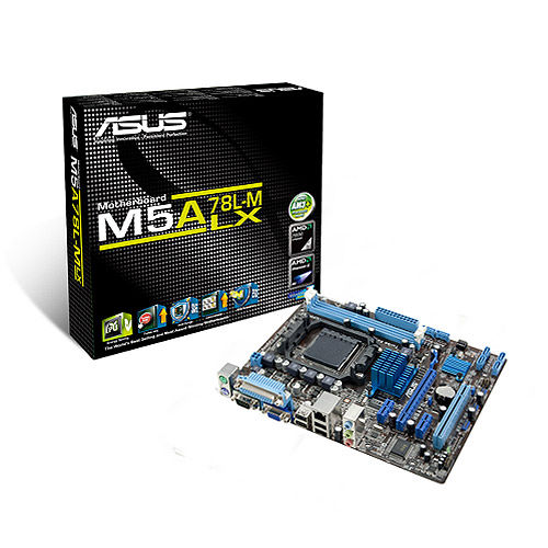
The previous Q6600 motherboard has some fault so it was not reused.  I got a deal on an AMD Phenom II 1055 6 core CPU and Asus M5A78L-M LX Motherboard from Microcenter in a bundle deal for around $100 about 6 months ago.  With such bundles, you are at the mercy of the bundle for the features of the motherboard.  But this one has a very good selection for a basic unit:
  • Integrated video (saving money and power on a video card).  VGA for switching.
  • 6 SATA ports
  • A legacy PCI card slot
  • Fair number of USB 2 ports.
  • mATX form factor - although the case can handle huge boards, if you don't need it, the space is welcome.
For a server, you want to minimize the amount of extras you add to save power and cost.   What I did end up adding, for features and because I had parts on hand:
  • 4 port USB 3.0 PCI-Ex1 card
  • 4 port SATA II PCI Card
  • 2 sticks of 4GB AMD PC3 memory that was on a deal from Slickdeals for $9.95/stick during the last low in prices.
I could have gotten a more modern motherboard with more capabilities but again I had "the bundle" deal and these cards were from previous server/PC upgrades so they were bought and paid for.  The PCI card will be a big bottleneck for server use but I only have a DVD drive and the server OS backup drive on it at present, freeing up motherboard SATA ports for real use.  The USB 3.0 ports are handy for external drives.  The card was a noname brand from the far east.  No driver disk found and WHS didn't recognize it.  A search on Google was sparse but led me to the VIA website where there were qualified drivers meant for manufacturers but they worked fine.

For drives, I wanted to get a few big ones and be done with it but I did not want to blow the budget if I did not have to.  The capacity needs were met after some scrounging - I had some 1 and 2 TB drives from an older HP Server and other uses.  I repurposed two 1 TB drives and two 2 TB drives for storage, putting them in a 4 bay caddy that was splurge #2 from Microcenter as it made placing drives easier than screwing them into the Armor case.  An older 750 GB drive serves to back up the boot drive.

So what did I use for the boot drive?  I had a 320 GB drive from the old PC that would have done fine as well as a 300 GB 10,000 RPM drive (but I wanted to keep that OS image).  Splurge #1 was getting a refurb 180 GB Corsair SSD on clearance at Microcenter.  WHS 2011 wants at least a 160 GB boot drive (although a hack will get that to 60 GB).  WHS can be pretty pokey when it comes to access especially the boot and console access.  That has always bothered me to an SSD was the way to go.  And it works, console startup is an order of magnitude faster.

I took my time on the hardware build, removing the old PC parts, getting all the dust out, getting the new motherboard ready with the CPU and stock cooler and RAM sticks.  The harder part was the drive caddy mounting and manufacturing an SSD mount from an old 2.5" bay insert as I was saving money from buying a commercial kit and the old 2.5 to 3.5 fat rails don't work with the SSD.

The cabling is as clean as one can generally make it if the motherboard mount does not have cutouts.  If this build was in my desktop Corsair case, the wires would be 98% hidden but this vintage case did not have those and I was not going to drill out large holes and ensure the sharp edges were taken care of.  That's ok - this is a server and not for show.  The airflow is not impeded by the wiring so all is good.  The case has a fan up front and back and a large side fan so for a server it's well ventilated (unlike my production server.  It's case was pre-active cooling so I rigged an intake fan in a nonstandard bay and out the back, it will be retired in the next couple years.

My choice of Windows Home Server 2011 is my own.  I have used WHS since it first came out, having used Windows XP for a server before that.  My home does not have any Macs and Linux is only on the electronics.  The WHS backup feature has saved the bacon a number of times and the file sharing works well enough for family use.

Time spent copying files off the HP Server not on the main server then all the server file shares to the new server.  I suggest Microsoft RichCopy (free and a bit newer than Robocopy but still 4+ years old).

I moved an external 3 TB drive off the main server used for backup of important files and placed it on the new server as the old server's USB3 drops the drives off every now and then.

So now we have our data on a WHS 2011 primary box with the new server as a server clone and the external drive as a last chance backup.  I am still weighing off-site backup alternatives, we have many files secure but it does not work in a dynamic environment.  With several hundred thousand pictures, cloud storage could get pricey.

So that's my setup for now.  Working on all of these issues was my main hobby for many years and I enjoy doing it but I have been away from the embedded electronics for too long and I have some cool items from YourDuino.com and Adafruit to get assembled.

Summer Lull and Where New Projects Are Being Posted

$
0
0
Summer has been rather busy around here.  With warm weather comes home improvement and three fair sized projects (deck, plumbing, foundation leak).

But I've still had time for electronic projects.  I received my Adafruit Trinket ATTiny85 based board and I was off connecting circuits.  This was a challenge, as many Arduino libraries do not work out of the box as the Tiny has fewer onboard hardware resources and limited memory.   So I started some posts on my progress, not here on the blog but on Google+.   It was faster.

Then I got "the e-mail".  Adafruit sent me a message stating they liked the work I had done on Trinket and asked if I wanted to write some tutorials.  Of course!  After formally asking work to ensure I had the ethics issues taken care of, I've started some articles, two of which have been posted.  My articles will appear in a group on this page.


Exciting, definitely.  So for fans of my open source posts, for now I suggest looking on the Adafruit Learning System for guides, mine will be there.

ABC Arduino Basic Connections the Book!

$
0
0
I have gushed over the circuit diagrams published by Alberto "Pighixxx" Piganti over the past few months.  He decided to collect them into a laminated bound book!

The campaign is on Indiegogo here.

Beautiful diagrams on every page


The campaign has already met it's goal and will make the book larger if they meet higher targets.  If you like building circuits but Making Things, this will help immensely.

Kicad: Making Your Own Circuit Boards

$
0
0
Last weekend, I took a class on using KiCad, the free, open source circuit board design program.  I hadn't made a board since high school using a Radio Shack etch-it-yourself kit.  To be honest, college was mostly wire wrap in those times.

The class was sponsored by WyoLum, held at the Nova Labs makerspace, and taught by Anool Mahidharia who had flown over from Mumbai with his bride to attend the Open Hardware Summit.

In the course of the weekend, we learned how to use KiCad, building a power supply, then building our own creation.

My design is at OSH Park now and should be delivered this week.  I will not spoil the surprise as there is a healthy chance there will need to be another set of revisions to get it where it should be.

I would guess I qualify now for the KiCad Skills Badge :)

Sensing Switches on an Analog Input, Including Multiple Key Presses

$
0
0
Many microcontroller projects quickly run out of pins when adding functionality.  The methodology used to continue to add functionality is to use expansion chips or share pins.  Many methods implement an approach that will register individual switches.  This article shows a method detecting single or multiple key presses.

One method recently written about at http://tronixstuff.com/2011/01/11/tutorial-using-analog-input-for-multiple-buttons/ uses a well known method of using one analog pin to register different values for different key presses.

This method is also used on various "LCD Shields" used to add buttons to an LCD display on Arduinos.

While these methods work well, they will not correctly register two buttons pressed at the same time.  For the first picture, if the far right button is pressed, the line is grounded and no further buttons will register.  Same for the second picture with the "RIGTH" button.  The reason is the button shorts out parts of the resistor "ladder".  Again, these work, but only give the lowest value to the analog pin.

For my next project, an alarm, I need to be able to differentiate between pins including multiple "buttons" at the same time.  The following is a schematic of what I will use to differentiate between 3 inputs:

The R4 pullup resistor can be the same as the internal pull-up on microcontrollers like the Arduino, enabled via 
pinMode(analogpin, INPUT_PULLUP); 
or 
pinMode(analogpin, INPUT); 
digitalWrite(analogpin, HIGH);  // set pullup on analog pin while the pin is an input.

On Arduinos like Uno, analogpin can be A0 to A5.  For ATTiny based boards like Adafruit Trinket and Gemma, you must use numbers 1 to 3 for the analog pin (GPIO #2 is A1, GPIO #3 is A3, GPIO #4 is A2).  Note the pullup does change the range of the AnalogRead.  See http://arduino.cc/en/Tutorial/AnalogInputPins for more information.

My application uses an Adafruit 5 volt Trinket.  In the schematic, Pin GPIO #3 (Analog 3), already has a 1.5 K ohm pullup to use USB, so no additional resistor is required.

For mapping values, you can read the analog measurement as various switch states are changed (your values may differ depending on resistor changes, pull-up values, etc.  You should take measurements on your own setup):

Switches   Value
Nothing    647
1 closed   397
2 closed   537
3 closed   576
1 and 2    320
1 and 3    342
2 and 3    457
All closed 283 

This works by using changing resistors in parallel along with R4 in series.  So if Switches 1 and 2 are closed, the resistance is (R1*R2)/(R1+R2) + R4.  See Wikipedia for a detailed explanation of resistor combinations.  This is also why the resistor values on the switches must be different - you are looking for unique resistances for each combination.  If you use the same values on the switches, the same analog reading will register for each key press.

The values do not have to be the same as the ones I used.  Avoid too small values to limit current to the analog pin.  Avoid values in the Megohm range as being too close to an open.  Values should not bee to close or too far from each other.  I suggest you wire the circuit up and measure the values - you want probably 10 or more between each registered combination.  The jitter (variability in reads) for me was about 2, so when you compare values you want to check like this:

int jitter = 3;
int readvalue;
int switchone = 397; // from table above for my circuit

readvalue=analogRead(analogpin);  // use your pin number

if(readvalue >= (switchone-jitter) && readvalue <= (seitchone+jitter) ) {
    Serial.println("Switch one is closed");
}

So for a project where you may have multiple key presses, you can sense them on one analog input by placing switches in parallel with differing resistors.


Intel Arduino Galileo

$
0
0
It's here.  The Intel based Arduino Galileo is finally hitting retailers.  I am fortunate enough to have a Microcenter nearby and they have them at the special price of $69.99 in-store limit 1.  They are currently also at Newegg.com and Mouser Electronics with availability announced by Adafruit.  The box:


The box is not that big, It is a bit longer but shorter than the full Arduino Uno box.  It is a bit deeper as it includes a AC to DC adapter and plug adapters for several countries (Europe, UK, Australia, US):


Looking at the board, it is smaller than the publicity photos make it out to be (always happens I would say):


I am told that retailers do not put rulers in their pictures because buyers ask where their ruler is when they get it - putting a quarter coin in there is even a stretch.

Here are the specs:

Galileo is designed to support shields that operate at either 3.3V or 5V. The core operating voltage of Galileo is 3.3V. However, a jumper on the board enables voltage translation to 5V at the I/O pins. This provides support for 5V Uno shields and is the default behavior. By switching the jumper position, the voltage translation can be disabled to provide 3.3V operation at the I/O pins.
Galileo is also software compatible with the Arduino Software Development Environment (IDE), which makes usability and introduction a snap. In addition to Arduino hardware and software compatibility, the Galileo board has several PC industry standard I/O ports and features to expand native usage and capabilities beyond the Arduino shield ecosystem. A full sized mini-PCI Express slot, 100Mb Ethernet port, Micro-SD slot, RS-232 serial port, USB Host port, USB Client port, and 8MByte NOR flash come standard on the board.
Detail of Intel Architecture Supported Features
The genuine Intel processor and surrounding native I/O capabilities of the Clanton SoC provide for a fully featured offering for both the maker community and students alike. It will also be useful to professional developers who are looking for a simple and cost effective development environment to the more complex Intel® Atom processor and Intel® Core processor-based designs.
  • 400MHz 32-bit Intel® Pentium instruction set architecture (ISA)-compatible processor
  • 16 KBytes on-die L1 cache
  • 512 KBytes of on-die embedded SRAM
  • Simple to program: Single thread, single core, constant speed
  • ACPI compatible CPU sleep states supported
  • An integrated Real Time Clock (RTC), with an optional 3V “coin cell” battery for operation between turn on cycles
  • 10/100 Ethernet connector
  • Full PCI Express mini-card slot, with PCIe 2.0 compliant features
  • Works with half mini-PCIe cards with optional converter plate
  • Provides USB 2.0 Host Port at mini-PCIe connector
  • USB 2.0 Host connector
  • Support up to 128 USB end point devices
  • USB Device connector, used for programming
  • Beyond just a programming port - a fully compliant USB 2.0 Device controller
  • 10-pin Standard JTAG header for debugging
  • Reboot button to reboot the processor
  • Reset button to reset the sketch and any attached shields
  • Storage options:
  • 8 MByte Legacy SPI Flash whose main purpose is to store the firmware (or bootloader) and the latest sketch. Between 256KByte and 512KByte is dedicated for sketch storage. The upload happens automatically from the development PC, so no action is required unless there is an upgrade that is being added to the firmware.
  • Default 512 KByte embedded SRAM, enabled by the firmware by default. No action required to use this feature.
  • Default 256 MByte DRAM, enabled by the firmware by default.
  • Optional micro SD card offers up to 32GByte of storage
  • USB storage works with any USB 2.0 compatible drive
  • 11 KByte EEPROM can be programmed via the EEPROM library.

You can see the PCI-E mini slot on the back.  I am looking to re-purpose a wifi radio from a laptop to test that out.

Comparison with other Boards:


The Galileo is upper left, going clockwise the Adafruit Wave Shield, the Adafrit Motor Shield version 2, and the Arduino Uno R3.  There is not much on shield compatibility, that will have to be part of upcoming experimentation.

What You Will Not Get in the Box


What is not in the box: USB cable (A to micro B), software, any parts or shields, no micro SD card.  There is only an Ikea-like diagram in the lid of the box and a hint to go to make.intel.com.

Information You Need to Know


The available resources for getting going with your Galileo as of this post:
I will be posting information on using this board, stay tuned.

Book Announcement: Getting Started with Trinket

$
0
0
Now you may officially know why I have not posted much in the last few months.  From September through December, I was writing tutorials on http://learn.adafruit.com as previously discussed.  I was contacted by Maker Media who asked for a book on the Adafruit Trinket microcontroller.  How could I refuse?  So I have been writing and writing some more.  Today Amazon now has it for preorder:

Getting Started with Trinket


The price will probably be a bit less than those listed as it will probably be edited down a bit more.

Hopefully it will be out for Maker Faire New York, September 20 & 21st.

More information and it develops.  Thank you to my viewers for your support of my projects.  Mike

Amazon Student

$
0
0

Amazon Student is a membership program created especially for college students.
Amazon Student members receive six months of FREE Two-Day Shipping with Amazon Prime on eligible purchases and e-mail alerts for discounts and promotions. Discounts and promotions will be e-mailed to your Amazon.com e-mail account or made available on the Amazon Student membership page at www.amazon.com/student.
Amazon Student members will automatically continue receiving FREE Two-Day Shipping with Amazon Prime when their free period is over with automatic renewal.  And it costs about half what Prime costs after the free trial period.
To consider joining, go to the Amazon Student pages.


The New Arduino Zero - The Good and The Bad

$
0
0

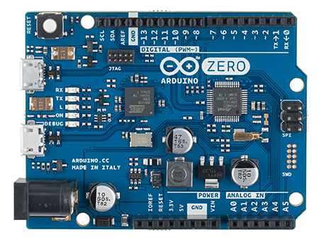
Enough articles are being produced on the new Arduino Zero, including the arduino.cc blog post and the press release, that I need not just repeat what others have written.

Today I compile comparisons on useful features, possible target audiences, and drawbacks.  If you believe I've missed something (or plain wrong), please post comments as a lively discussion would be good.

Target Audience:

  1. Adopting the Arduino shield pinout would imply that use of the hundreds of Arduino shields in existence would be expected.  Great, but it doesn't imply this at all and this will confuse new folks.  The voltage at which the pins signal is at 3.3 volts, not the Arduino Uno's 5 volts.  So you can count the number of 3.3 volt shields on maybe two hands and the number of autoswitching 3.3v/5v shields on one hand.  This, coupled with the paltry 7 milliamps per pin and this is not a beginner's board (drawing too much current would damage the processor and it is not replaceable like the ATmega 328p on most Unos).
  2. Debugging port is definitely an advanced feature and very welcome in more powerful boards.  Anyone doing more than  a "Hello World" program knows that stepping through code and watching what it does is professional programming, something possible 30 years ago on other processors.  This can be for seasoned coders and for beginners with very good instructions and a well-written IDE like the Adafruit python program for Raspberry Pi.
  3. The 32 bit SAM D21G processor has a whole host of capabilities - ARM Cortex-M0+ based microcontroller with 256KB Flash, 32KB SRAM, 48 MHz, three 16-bit timer/counters, DMA, USB Host and Device, real-time clock, 14 ADC, 10-bit DAC, 21 PWM capable digital pins, 6 UART, 6 I2C, 6 SPI (38 total pins).  Using the Leonardo header pinout, only a small fraction of the chip's power is exposed.  Kind of a waste as posters to forums state they would like to use the whole chip.
  4. Documentation states a target with the potential to realize truly innovative ideas for smart Internet of Things (IoT) devices, wearable technology, high-tech automation, crazy robotics, and projects not yet imagined.  The platform is ill-suited for wearables, and awkward for many IoT applications due to the limited pinout.  Translating this board to a finished product is much harder due to the large, complex chips it uses.  For robotics and automation, this board holds promise but I'd still like full access to all the SAM D pins.
Benefits:
  1. Eventual shield compatibility once the manufacturers gear up new boards.
  2. Much more memory (program and RAM) for more advanced program capability
  3. Much faster (48 MHz) and more efficient (32 bit processor)
  4. Debugging support
Perceived Problems:
  1. Limited by the few exposed pins in the Leonardo/Uno header pinout
  2. Big - the Leo/Uno size makes it harder to use in embedded applications.  If it was meant only for prototyping, more pins should be available.  If a learning tool, the size is fine but the fragility of the processor is of concern.  
  3. Taking lessons from Arduino Due, if the standard libraries are not present in software, porting older programs for use on Zero will be very hard.  One of the strengths of the older architecture is AVR code compatibility.  Arduino team support for ARM code, while well intentioned, has been glacially slow.  The test: will code for modern digital LEDs run on this with only minor issues?  It is such a pervasive use case, one would hope so.
The big variable: Cost
If this board is competitive price-wise with Raspberry Pi ($35) then it can be a winner. Even better would be for it to replace the Uno price of $29.95 and the Uno would drop down to the expected $17.50 or so.

Software:
The new debugger will be a welcome step up from the old Processing/Wiring IDE of today.  Atmel makes some very, very good software, modern tools but often more technical than beginners can use.  Hopefully the IDE work will translate to the whole Arduino product range as the fragmentation of versions to support other boards has grown out of hand.

Glimmers of Hope:
The Arduino Leonardo has not been a rather successful board but it set a benchmark for the community to use a form factor and software that has evolved into very good third-party products.  Perhaps this is a similar board - one that by itself will not be particularly successful (but probably more so than Due), but will establish the Atmel SAM processors as the successors to the AVR architecture.  The test will be if third-party companies come up with better boards than the Zero but still be compatible with its features.

As details come out, perhaps some of what I have said will not be necessarily pertinent but I think I have the general direction. On real data, we have little to go on until Maker Faire San Francisco in a couple days. 
Until then you can read the sparse Zero product page and the SAM D 21 Microcontroller information.

Your Perfect Microcontroller

$
0
0
With thoughts of the Arduino Zero floating around, it begs the question: has anyone done any customer surveys to know what type of microcontrollers people actually want to buy?  Ask customer?
I'm sure certain companies have listened to the market.  Limor Fried of Adafruit has a good track record for introducing controller form factors that are popular.

The Arduino Zero is a collaboration of Atmel and Arduino.  But nothing that has come out to date has said "we introduced this specifically targeting the customers for ______".  There is some market-speak for Internet of Things and wearable usage.  Who is going to put an Arduino Zero board in a wearable?  If it costs $5 then people will try but this thing is shaping up to be big and probably at a price point that hurts.

So I open it up: if you had your choice of a perfect microcontroller board, what would you like to see?

Ideas:

  • Large, small, "medium", compact, cubist, "fits in a ___"?
  • Lots of input/output pins?  Just enough?
  • BIG ONE: 5 volt pins or 3.3 volt pins? (or 3 volt, 5 volt tolerant!)?  Current per pin (Zero's 7 milliamps, Uno's 40 milliamps, or other)?
  • Interfaces (serial, I2C, SPI, CAN, Ethernet, debug, USB)?
  • Power?  Solar, LiPo/battery, 5 volt, 3.3 volt?
  • Bare metal real-time software (Uno etc.) or Linux, both, other?
  • Other features?
In a following post I'll compile a user-desired board and my next dream board.

Getting Back to Blogging after Publishing the Book

$
0
0
As blog readers are probably aware, I have been working on a new book for Maker Media called Getting Started with Adafruit Trinket.  It's been a labor of, well, work.  It has been a great experience but I'm ready to get back to a wider array of projects.

The book details use of the Trinket - an ATtiny85 breakout board from Adafruit Industries.


Here is the back and front cover.  It has changed over the last few months, the title a bit, the cover definitely new and a departure from many Make books.  Another departure is color - the inside is printed in color vs. black and white for most Getting Started books.  This allows you to really see the wiring and the projects.

The source code and the illustrative pictures have been posted on GitHub at https://github.com/trinketbook/GettingStartedWithTrinket

If you would like to see the Adafruit "Ask an Engineer" webcast in which I join Limor "Ladyada" Fried and Phil Torrone talk about many things including the book, here is the video:


Please excuse my actions and the bags under my eyes!  I had been awake for like 22 hours at that point and I need my beauty sleep after 16!  Curse transatlantic flights!

The book is available in final release via ebook in  ePub, Mobi, and/or PDF formats from O'Reilly at http://shop.oreilly.com/product/0636920031598.do or preorder the paperback from Amazon.com.  It should be out by mid-October!

Making a Flexibly Powered Qi Charger

$
0
0
Just out yesterday: is a way nice Qi Charging module from Adafruit Industries.  This module allows you to hack together an inductive charger with input from multiple sources.  So I have looked at some methods to power the Qi charger:


  • The standard wall transformer for mains to 5 volts
  • A mobile Qi charger powered by a LiPo Battery
  • A solar powered, LiPo backed Qi Charger
The last two methods allow you to take your Qi charger away from the wall - out and about.  Here are some diagrams for all three methods:


Each of the methods should be connected (individually, not together - that's an either-or arrow) to the Qi charger.  Different LiPo batteries can be used with more or less capacity.  

Pretty much all of the Qi chargers I have seen have a wall connection - they have not been imagined as a mobile device, as most of the Qi chargers (well...) charge a mobile device.

The next article will look at methods for using a Qi receiver module and what we might want to do besides charge our phone or tablet.  Ideas?

Qi Portable Power Receiving

$
0
0
In light of the new Adafruit Qi Transmitter, I diagram how you would design a Qi power receiver system.

The diagram shows the transmitter and a small, thin receiver built into a credit card size device with a micro-USB jack.  The card-size receivers are actually rated about 100 milliamps greater (600 ma) than the regular Qi receiver coil, Adafruit 1901 (500 ma).

You can plug the receiver directly into something needing power but that juice will go away when the receiver gets more than 8 millimeters away from the transmitter. 

To keep your project powered when the receiver is not powered, you can use the Adafruit Powerboost 500 C to regulate power and provide "off-grid" power with an extra LiPo battery.  Power will be available to the project and charge the battery simultaneously when the receiver is near the transmitter.  When the receiver is moved away, the Powerboost relies on the battery with very little transient changes (to quote Ladyada: "we did this by engineering the heck out of it (the Powerboost)".

Applications


What can you do with a Qi system?  Let's see:

  • Obvious is cell phone and tablet charging (what Qi was designed for)
  • Recharging your projects without plugging them in.  This could include:
  1. Firewalker shoes and other wearables
  2. Electronic Stuffed Animals
  3. Prop accurate projects (where a USB jack would be "unsightly")
  4. ... and more

Another idea is transmission of power through a window.  Why would one wish to do this?  Many people live in rented spaces where holes through exterior walls are not allowed.  Or maybe a homeowner does not want a hole in their house.  Placing a Qi transmitter on the inside and a receiver outside, you can get your project powered outside.  Just be sure the glass space is 2 to 8 millimeters, more than 8 millimeters is outside the Qi spec.

What uses do you see for Qi powering your Maker projects?
Viewing all 157 articles
Browse latest View live